I’m going to do my best here to break down some terms, ideas and principles behind 3D asset creation, but this is by no means a comprehensive guide – rather I’m just going to talk about the different concepts and important ideas, so that the terminology and workflow will be easier to understand. I’m going to be using Maya in all the images, but these ideas stretch across all 3D modeling software (although CAD based software operates a little differently.) I’m also going to focus on things that are important for VR and game dev specifically, rather than high-end animation. I will bold vocabulary words the first time I use them in the text.
Modeling and Meshes
Creating any 3D asset always starts here – once you have your concept idea (maybe some sketches, or just an idea in your head, or a real world item you’re copying) the first thing you are going to do is create a polygon mesh (there are other ways to create meshes that have different strengths and weaknesses, but in general, polygons are the way you’re going to want to go for VR/game dev)
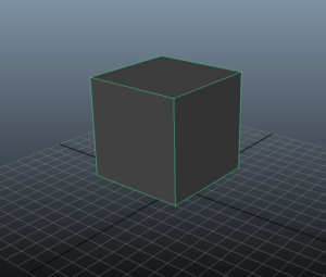
The simplest example of a polygon primitive is the plane – but the most useful is probably the simple cube. Think of a polygon as being a face of any object – in 3D modeling, every object is made up of faces (at least usually – again, there are other categories that I am not going to go into within this tutorial.) A primitive is one of a variety of basic ‘starting point’ shapes that modeling programs include. Others would be a plane, a sphere, a torus, a cylinder, etc. So in a cube, there are six polygons. We can also refer to an object created from polygons as a mesh, or polygonal mesh.
From here it’s possible to create basically every object that you can think of, with a few modeling tools.
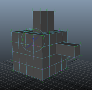
The components of the mesh are pretty simple – each face of the cube is a polygonal face. Each green line you can see above is an edge, and the corners where those edges meet are vertices.
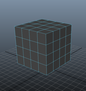
All of those things can be moved around, scaled, rotated, etc, to create new shapes. It’s also possible to add divisions to a primitive, to give you more to work with – e.g.
Another way to add complexity is to use an extrude tool. What this does is allow you to select a face or an edge, and pull a whole set of faces and edges out of it – e.g.
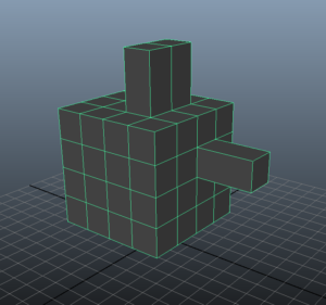
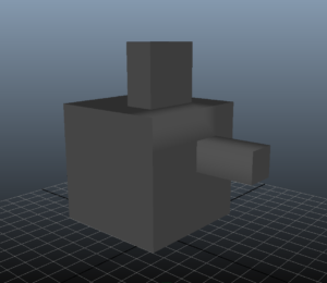
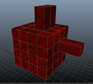
In this case, I selected three faces, and extruded them out. I could also have scaled, moved or rotated them – but now, where there was just one face, there are four more faces. There are a lot more modeling tools available to you depending on the software package, and I encourage you to experiment, but this is one easy way to build things – extruding, and then manipulating edges, faces and vertices to get the shape you want.
Polygon best practices
Bear in mind when modeling for games or for VR/AR, what you’re doing involves real time rendering – the hardware you’re using has to evaluate and display everything you create in real time. When it comes to polygons, that means using as few as you can get away with – if you have a cube with 6 faces on screen, that’s a lot cheaper than having a cube with 600 faces. Obviously building an entire scene solely from 6 sided cubes might not be what you want, but it’s worth thinking about what your polygon budget is for any given scene – benchmarks for VR are usually something like 20,000 to 100,000 polygons for a scene. So use as few as you can.
Other things to be aware of – a game engine like unity turns every polygon into a triangle, and your life will be much simpler if you avoid the use of polygons with more than 4 sides. An n-gon with 6 or 7 sides might seem more elegant sometimes, but will actually make your life harder in a few different ways. Stay simple, use quads and tris.
Materials, shaders, textures and normals oh my!
Whatever renderer you’re using, it has to be able to decide what every pixel on the screen looks like. It does this doing lots of complex math based on lighting and a variety of other things. Right now, your model is a collection of faces that are a hollow shell. Each face has an associated normal. This is an imaginary ray that points out from every face, and defines which is the front or back side of the face (most faces in 3D modeling are one sided- which means that they’re invisible from the wrong side.) Normals also govern how imaginary light rays hit the object, so editing them using a normal map lets you add complexity to your model that doesn’t require additional polygons. A normal map is a 2D image that wraps around your 3D object. The colors on the normal map don’t translate to colors on your object, they translate to edits to the normals.
Vertex normals displayed above – the small green lines radiating from each vertex.
In the above image, I selected two edges and “softened” the normal angle – you can see how that’s changed how we perceive the edge, even though the geometry of the cube hasn’t changed at all. A normal map is a more complex way of doing this – more on that later.
A Material is something you assign to a mesh that governs how that mesh responds to light. Materials can have various qualities –reflectivity, specularity, transparency, etc, but basically a material is what your object is ‘made of.’ E.g. if I want something to be metal, metals have certain properties that are different from something I want to appear plastic, or wood, or skin. Examples of simple materials are things like lambert, blinn, phong. Bear in mind, a material is not color information, it is how something responds to light.
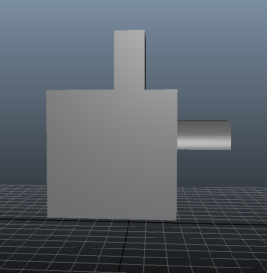
Here’s the same shape as before, with a more shiny blinn material applied – the previous examples were all lambert.
A Texture is where your color information comes in. A texture can be a simple color, or it can be something generated procedurally, or a 2D file mapped to a 3D object. Here are examples of each of those.
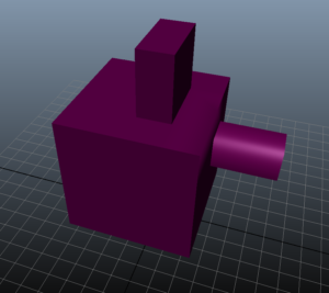
Simple color information (note, we still have the ‘blinn’ material here, which is why this is slightly shiny)
A simple procedural noise texture – this is something generated by the software based on parameters you pick. Notice how the pattern is oddly stretched in a couple of places – more on this later.
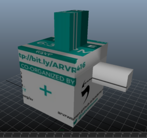
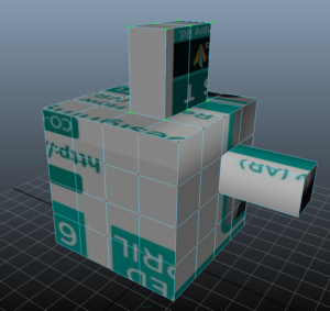
Here’s a file based texture – where a 2D image is mapped onto my 3D mesh. Notice again how there are places where the text is stretched oddly.
Final definition for this section – a shader is the part of your 3D software that takes the material, mesh, texture, lighting, camera and position information, and uses that to figure out what color every pixel should be. Shaders can do a lot of other things, and you can write them to do almost anything you want, but mostly this is something I wouldn’t worry about until later.
UV maps and more on textures.
Remember in the previous section how those textures I applied were a little wonky in places? That’s because I hadn’t properly UV unwrapped my object. A UV map is what decides how your 2D image translates to your 3D object. Think of it like peeling an orange – if you peel an orange, and lay the pieces out flat, you end up with a 2D image that describes your 3D object.
Here’s what the UV map from my last image looks like right now.
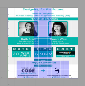
You can see that there isn’t really any allowance made for my projections from the cube – what is here is just a cube map – and maybe some of the data I wanted on object isn’t displayed at all – like the faces of my event speakers.
How a UV map works is it assigns every vertex on the object to a corresponding UV. What that means is that each face then knows what area of the 2D texture image it should be displaying – and the software will stretch that image accordingly.
If I remap my cube properly, here’s what it looks like
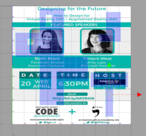
You can see now that I have my base cube, and I’ve separated out the projected pieces into their own maps – that’s why there are holds in the base cube, because that’s where those maps attach. I’m not going to go into the different ways you can unwrap objects, because it’s a fairly complex topic, and there are a lot of different ways to unwrap something, but in general, you don’t want to stretch your textures, and you want as few seams (i.e. separate pieces) as possible. It’s also possible to layer UVs over one another, if you want to use the same piece of a texture multiple times.
Here’s what the remapped cube looks like now – no more odd stretching.
Final note on file textures – they should ALWAYS be square, and always a power of two number of pixels per side – e.g. 256 x 256, or 1024 x 1024.
(also side note, if I was actually using this as a production piece, obviously I’d be taking more care with the image I used, instead of using a promo image for our recent event)
Normal Maps, Bump Maps, Displacement Maps
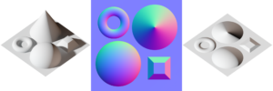
All three of the above are ways of using a 2D image to modify the appearance of a 3D mesh. A normal map can be seen below. In this case, the image on the left is what we’re trying to represent, the image in the center is the map, and the right shows what that looks like applied to a 2D plane – it appears to have depth and height values, even though it is a single plane.
A bump map does something similar, but uses a greyscale image to calculate ‘height from surface’ values. A bump map is very useful for doing what it says in the name – making a surface appear bumpy or rough. The thing to note with a bump map is that it doesn’t affect the edges of an object – so an extreme bump mapped plane seen from the side will just look like a plane – no bump information
A displacement map is similar to a bump map, but does seem to affect the calculated geometry of an object – ideal for adding complexity, but not usually supported in game engines. Most game engines support normal mapping as the way to add depth information to polygonal objects.
There are other types of map too, that govern things like transparency or specularity, but those are beyond the scope of this post.
Rigging!
So now we have a lovely cube, with a material and texture. If your asset isn’t intended to be have moving pieces, at this point you’re done – you’ve built your table, or chair, or book. Any animation you might do on it probably will just move the entire object. If this is not the case, however, if what you have is a character or a car, or a robot, you’re probably going to want it to be able to move.
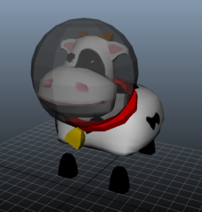
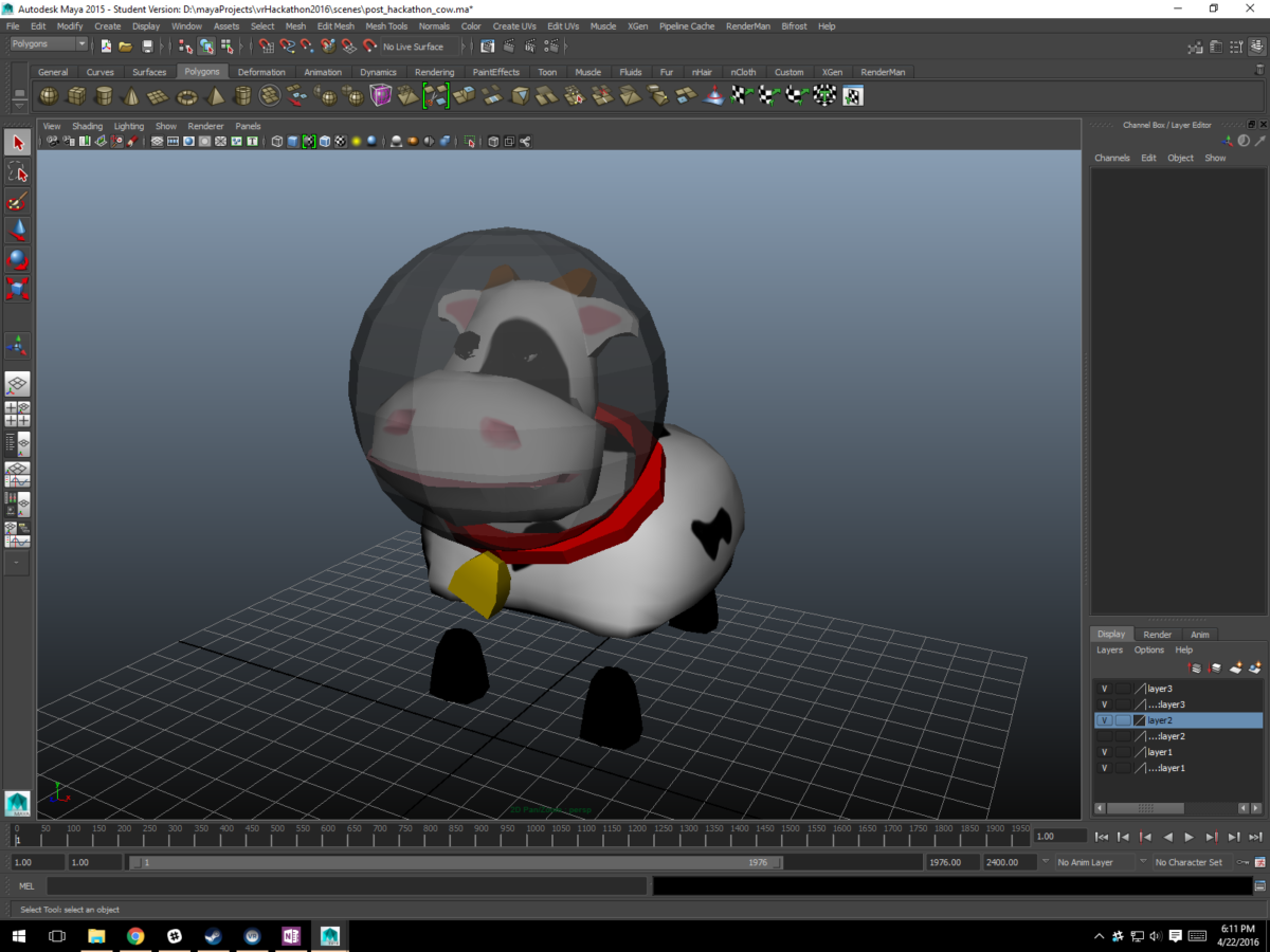
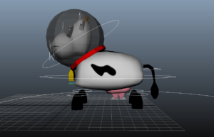
Here’s SpaceCow. SpaceCow animates – her head and legs and body and udders all move. And that’s because I built a rig for her – a skeleton and set of controls that move that skeleton around, and that define how the skeleton moves the mesh. Rigging is a vast, deep and complex subject, so I am not going to go too far into it right now, I’ll just show you what a rig looks like and explain very briefly how that works.
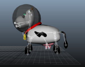
In this side shot, you can see white triangles and circles which show the joints that make up SpaceCow’s skeleton. Every part of her that I want to be able to control has a joint associated with it, and those joints are attached together in a hierarchy that governs which ones move when other joints move.
In order to animate SpaceCow, I want to be able to control and key those joints – assign specific positions at specific times or keyframes.
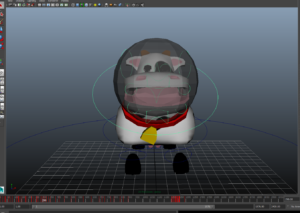
So I build a control structure for the joints that consist of simple curves that I can move around easily.
If I hide the joints, that structure looks like this
The white lines here are the control curves – each one lets me move around different parts of the skeleton. The very large line around the whole cow lets me move the entire cow, too. There are other parts of rigging that define how the mesh attaches to the joints, but that isn’t important now. If you want to learn rigging, I highly recommend Jason Schleifer’s Animator Friendly Rigging, but there are a lot of other great resources out there.
Animation
Once you have a rig in place, you can move on to animation. Animating is done by assigning keys to specific frames along a timeline. That means that for any key, I can set the properties of position, rotation, (and sometimes scaling).
In the above image, I have selected the curve that governs SpaceCow’s head. The timeline at the bottom of the image shows all the keys I’ve set for her head movement – each red line represents a key that I set. The position between each key is determined by curves that interpolate smoothly from one to the next – so if my x rotation starts at 0 at frame 1, and ends at 90 at frame 100, at frame 50 it will be around the 45 degree mark. Again, this topic is more complex than I have time to go into, but this is the basics of how this works.
Conclusion
Thanks for wading through this – I know this ended up being a long document, partly because 3D asset creation is a complicated subject. Hopefully you should at least understand the basic workflow (the topics appear in the order of operation) and how everything fits together, if not how to do each specific thing. Please let me know if you are confused by any of this, or if any information is inaccurate in any way.
Thanks for reading!
Suzanne